
CHIN LAN RUBBER ENTERPRISE CO.,LTD.

Quality、Reliable、Satisfaction
OVER 48 YEARS IN RUBBER MANUFACTURING SINCE 1975
Mould Design:
The mould design is an essential part of product quality. With the correct mould design and an optimised rubber formulation, it is possible to produce products of world class quality. The choice of press makes that task either easier or more difficult, and has to be made on the individual requirements of the mould and the manufacturing environment.
Sizing of Moulds
The first stage in mould design is to determine the overall size; a task governed by the dimensions of the press platens to which it will be fitted. In an ideal world, the mould should be able to be sited on the platen within the effective heating area. This generally requires an outer margin of three to four centimetres. Modern press platens are usually equipped with a ‘guard zone’. This allows the outermost parts of the mould to receive additional heat, which compensates for losses from the exposed outer surfaces.
The design of the moulding tool is determined from the shape of the components that will be produced. For this reason it is of prime importance that the designer of the components works closely with the tool designer and the moulding technologist. Co-
operation at this level is vital to produce a tool design that will work well in production.
The number of cavities is determined by:
• The maximum shot volume of the injection press
• The component volume
• The maximum projected area of the component
• The clamping pressure
• The injection pressure
• The required production rate
Failure to recognise these constraints will result in collapse, or delay, of the project [1].
Runner System
Cavity layout will determine that of the runner system. For best operation, the cavities need to fill evenly and at the same time. Uneven filling often results in components that are ‘light’ and with runner systems that are heavily ‘webbed’ with thick flash,
which is the result of high pressure build up before filling is complete. Each cavity must have a runner path length that is identical, or ‘balanced’. Some cavity layouts have a runner system that will be inherently balanced, whilst others will need to be
carefully designed to ensure balance. An example plan view of a balanced runner
system is shown in Figure 1.1.
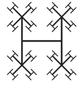
Example of a balanced runner system
A general, though not absolute, rule is: if the number of cavities (N) is such that N=2Y (1.1)
where Y is an even number, then the runners to each cavity can be fully balanced without difficulty. Where Y is odd, then balancing becomes more difficult and the task is best achieved through the use of rubber flow modelling programs. A number of computer
packages have been designed for this purpose and their use is strongly recommended to ensure that a mould that will work first time in the press. The sizing of the runners can be rapidly achieved through the use of a factorial designed experiment that is run
using the rubber flow modelling programme. The author has successfully used this method for many years using the Fillcalc IV programme [2] (see later), as do a number of mould makers. For this programme to run on modern computers it may be necessary
to operate a dual boot system using an earlier version of the computer operating system.
An alternative solution may be to use a cold runner system that feeds each group of cavities directly. Such systems work well with components with cross sections of a few millimetres.
The way that the rubber flows through the runner system, into the cavity, has a profound influence on the properties of the moulded component. This subject will be discussed in greater depth when reviewing the moulding process. At this stage the
reader should be aware that there are aspects of tool design that affect rubber flow, and that, once the mould has been produced, the effects will be costly to correct, both in terms of tooling changes and the loss of production and customer confidence.
Balancing of the runners is the easiest of the technological problems to solve. A designer also has to take into account the rate of flow of the rubber. The flow rate changes with every branch that occurs in each of the limbs of the runner system and this
affects the pressure gradient that develops during the injection phase of the moulding cycle. The pressure gradient will also vary with the rate of injection. The faster that the rubber is injected, the greater will be the pressure gradient, and the less scorch
as shown in Figure 1.2.

Effect of injection time on pressure gradient and scorch
The maximum pressure gradient that can be tolerated will depend on the maximum clamping force available to keep the mould in a fully closed position. The sizing of each of the limbs of the runner system is therefore critical to the operational running of
the mould. Optimal sizes may need to exceed those normally used. The cross-sectional area of each part of the runner needs to be in proportion to the rubber volume that it needs to conduct and compensating for the additional resistance to flow imposed
by longer paths. Use of undersized runners and gates leads to component faults such as ‘light’ parts and other problems ranging from minor ‘weld’ or flow fronts to faults that will seriously affect the component service life.
The cross-sectional shape of the runners is not critical provided that the cross-sectional area of the runner is not substantially greater than the equivalent round section. Trapezoidal or modified trapezoidal sections have a great deal to offer in terms of
the control possible for the position of the runner when the mould opens, when they stay with the greatest surface area in contact with the mould. Flat section runners generate high-pressure differentials and engender the risk of scorch.
2.1 The Sprue Bush
The design of the sprue bush is important to the working of the mould. It is best made so that it can be readily changed or adjusted to suit different presses or in the case of damage. The sprue should be a smooth cone, increasing in diameter from the
open until it meets with the runners. At this point it should blend into a round boss of sufficient diameter to readily accommodate each limb of the runner system. At the base of the boss it is useful to incorporate an undercut feature to ensure that the
cured sprue will be withdrawn from the nozzle as the mould opens. Use of too small a nozzle is a common cause of ‘light’ components, due to pressure loss in the runners.
In extreme cases high temperatures generated by small nozzles will result in scorch with attendant problems. A common complaint with this approach is that too much rubber is wasted in the runner system. It should be noted that rubber ‘wasted’ using
these principles in the design of the runners will prevent costly rejects.
2.2 Injection Gates
The gates form the final restrictive pathway connecting the runners to the mould cavity. The gate design can be used to impart a heat increment to the rubber as it passes through, although this must be balanced by the need to allow the rubber to
flow and fill the mould in a suitably short time. It should also be small enough and suitably placed, so that when the mould opens the rubber will break off neatly and easily. It should be sited so that it does not affect the function or appearance of the
component. The orientation of the cavities and the siting of the runners also affect the positioning, shape and size of the injection gates. The gate section is usually the same as that of the runner, but smaller. Flow modelling will determine whether the
gate is too narrow, which causes scorch, or too wide which causes a low temperature
of injection, and a longer cure time.
For components of irregular shape the flow path may have to divide and then re-join. It is at the meeting of two flow fronts that air traps and weld lines can be formed. If flow fronts are bound to meet, the gates should be positioned so that the fronts are
pushed to the part of the component that is likely to be the least stressed in service. If possible a vacuum gate should be sited at the point where the fronts meet so that the initial weld front and associated gases can purge from the cavity into the vacuum
runner (see Section 4).
For some moulds it is appropriate to site the gates at the cavity parting line. Two approaches may be used in these cases. The first is to employ wedge shaped ‘fan’ gates. These taper from the runner section to a slot shaped aperture that may be 0.2 to
0.5 mm in height and three to four times the runner diameter in length. The second way is to use a ‘subterranean’ gate that consists of a simple angled cylindrical hole that joins the runner to the cavity at a point several millimetres below the parting
line. The junction between the gate and the runner needs to have a well-formed radius to ensure the rubber does not break at this point when the component is extracted from the cavity.
3 Air Removal
Moulders that experience air trapping problems will know how difficult it is to cure this problem when in production. It is a fault best avoided at the design stage.The problem arises when the mould is filled so fast that the air within the mould does not have time to escape, or where converging rubber fronts meet. Trapped air causes light parts, and may cause localised oxidation of the rubber, seriously affecting component quality. Some component shapes will inherently produce air or gas traps.
With a bonded system gases arise from the heated metals and the hot rubber produces vapours as it begins to crosslink. In such cases it is possible to reduce or eliminate the effect by using a vacuum system, with vacuum ports sited at, or as close as is possible to, the last point in the cavity to be filled, to remove air/gas from the mould before and during the injection phase. This method is a better solution than the traditional ‘bumping’ of the press, when the mould is opened minutely a number of times at,
or shortly before, the end of injection. Bumping allows the relatively uncontrolled release of rubber from the cavity and can seriously reduce cavity pressure, leading to components with significant micro-porosity. Computer modelling of the cavity can
be used to predict where gas traps are likely to occur.
4 Modelling Software
Flow modelling software has been available for a number of years. With experience and knowledge of the technology of rubber processing, it is possible to study how rubber will flow and react in a two-dimensional representation of the mould. This
allows the mould to be investigated, on the computer, for a range of conditions and with trial positions for gates. Used in conjunction with factorial experiments, it is thus possible to optimise the mould design and its operating conditions, before the
mould is made! This approach really works and permits the manufacture of moulds that work the first time they are put in the press, saving wasted material, time and money. Several different flow modelling systems are currently available and should be
used as a regular tool in the design and development stages of every new mould [2].
5 Ejector Systems
To ensure ease of operation, many moulds are designed with ejection systems that allow the components to be ejected automatically as the mould is opened. The precise design of the mechanism varies according to the shape of the cavities and the way they are arranged within the mould bolster. The ingenuity of the mould designer may have no bounds but it is worth noting that there may be a price to pay. The price relates to control over cavity temperature and cure. Internal ejector mechanisms require voids to be maintained in the body of mould in order to house the operating cams and levers. This interferes with the heat flow to the part of the cavity that is directly joined to the ejector. The temperature gradient between the heating platen and the
cavity is usually of the order of 10 to 15 °C. Internal ejector mechanisms can cause the gradient to double that value, leading to high differential in the cure between different parts of the moulding. External ejectors should be designed to avoid the need
for areas of the hot mould to be in contact with cold ejector bars since this causes heat loss problems in the mould. Insulation of the contact surfaces of the ejector bars with resin-based boards is often beneficial.
6 Flashless Mouldings
The moulder aims to achieve a moulding without flash. Flashless injection moulding has been made possible through the building of moulds with extremely close tolerances that are capable of resisting very high pressures at mould seam lines. Such accuracy
produces flashless parts. A new technology for flashless moulding of rubbers has been developed. It involves extremely precise dosing of the injection volume in relation to the mould, together with a very accurate alignment of the clamp platens and high
precision mould manufacturing. The system eliminates post-moulding operations, whilst also avoiding possible damage or part quality problems associated with part demoulding and deflashing.
7 Mould Monitoring Points
Wherever it is possible moulds should be provided with pockets for temperature measuring and recording instrumentation. This is essential if the moulding conditions are to be properly optimised and also provides a thermal ‘finger-print’ for audit of
the process during the production cycle. Surface temperature probes are better than nothing, but give results which may well differ between operators and are affected by the condition of the mould surface.
8 Mould Materials
New moulds may produce parts that are essentially flash free but gradually deteriorate with use. A low rate of wear depends upon the right choice of tool steel. This should be a grade that can be hardened by heat treatment but without any attending distortion. The design specifications of the mould must include details of the materials from which the mould cavities and the mould bolster will be made. Failure to understand the reasons behind the choices may lead to substitutions of materials that are thought to be similar, but in reality have significantly different properties.
The mould bolster comprises the bulk of the moulding tool and forms the matrix that supports and locates the cavity inserts. The bolster block also encompasses the runner system. The metal of construction must reflect the working needs of the mould.
These may be summarised as:
• Adequate compressive strength to withstand any tendency to deform under pressure.
• Good machinability, enabling the tool maker to shape it with minimum wear to the cutting edges of drills and milling cutters, and in the minimum time.
• Resistance to warping during machining and hardening operations.
• The ability to be hardened to a level that renders the finished tool insensitive to denting and the general hard wear of the production environment.
• Resistance to corrosion results in lower mould maintenance cost and a clean
surface after the hardening process.
• For the bolster it is unnecessary to use steel capable of taking a high degree of
polish.
References
1. L. Sors, Muanyag es Gumi, 1995, 32, 2, 35.
2. Fillcalc, Version 1.07, RAPRA Technology Ltd., Shawbury, Shrewsbury,
UK, 1995.
3. Rubber World, 1987, 197, 1, 85.
4. MacPlas International, 1999, 1, 58.
5. Plastics and Rubber Weekly, 1984, 1040, 12.
6.Practical Guide to Rubber Injection Moulding